|
|
Clearance
100% Collision-Free
Assembly
Tool-Free Clamshell
Flywheel
Brass + Block 'O'
Interactive 3D Inspection
Drag with one finger to orbit • Pinch to zoom
Loading 3D CAD Assembly...
Assembly Progression
Swipe horizontally ➔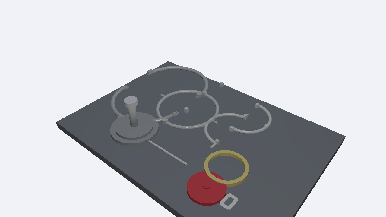 Step 1
Knolled Layout
All 11 modular components laid flat on workbench.
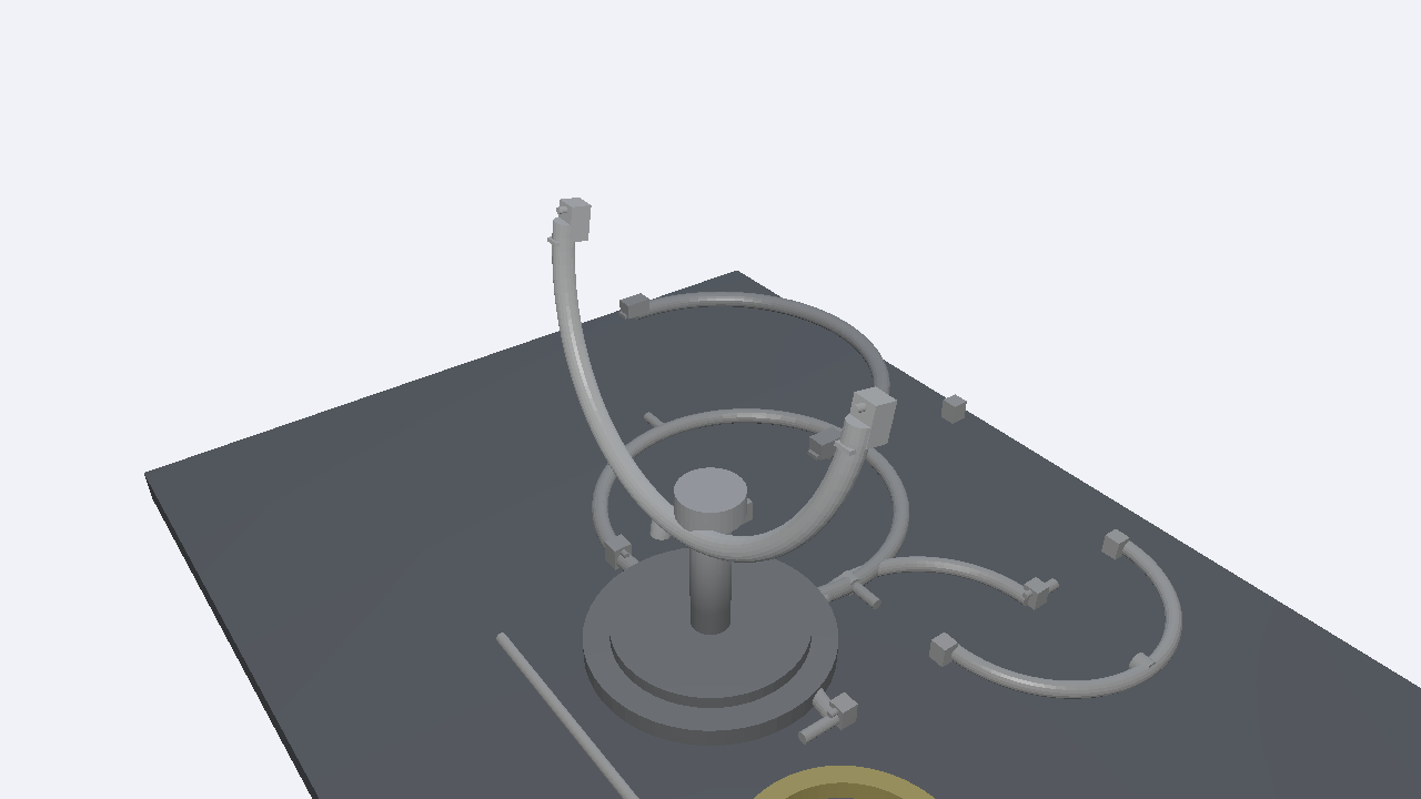 Step 2
Base Pedestal Docking
Pedestal stands upright; lower cradle docks into stem cup.
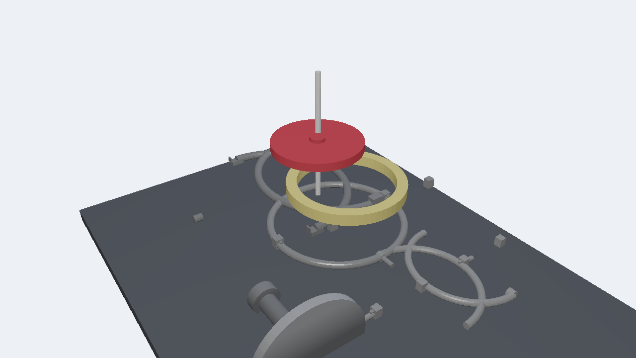 Step 3
Rotor Concentric Press-Fit
Spindle, brass rim, scarlet core & Block 'O' unite.
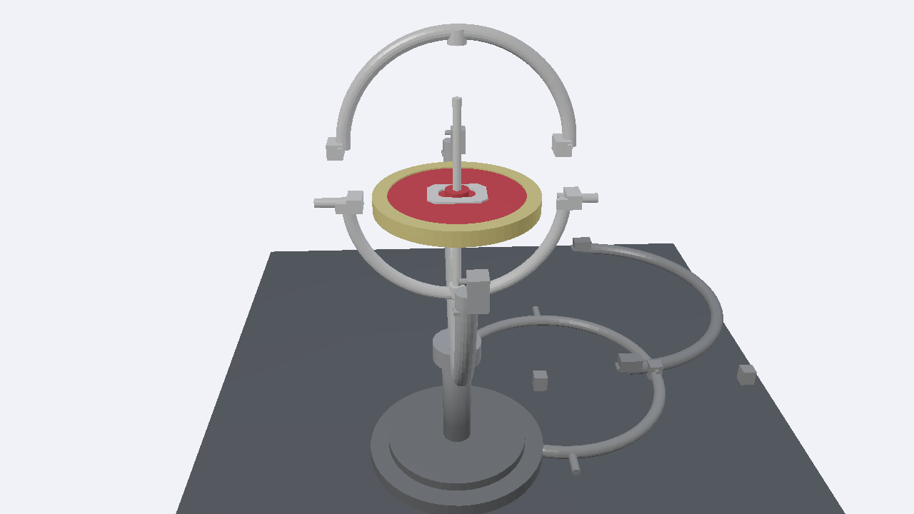 Step 4
Inner Gimbal Clamshell Snap
Upper arch descends, locking spindle into jewel cups.
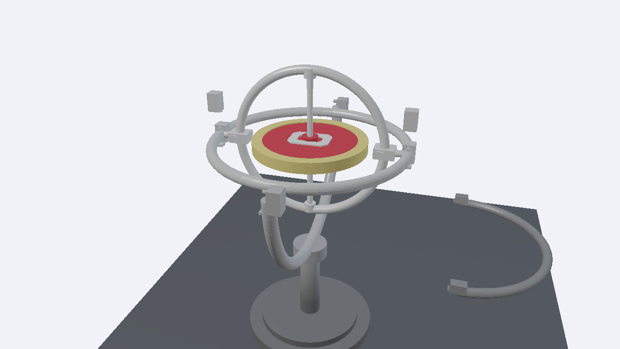 Step 5
Outer Gimbal Capture
Z-pins drop into saddles; upper caps snap down.
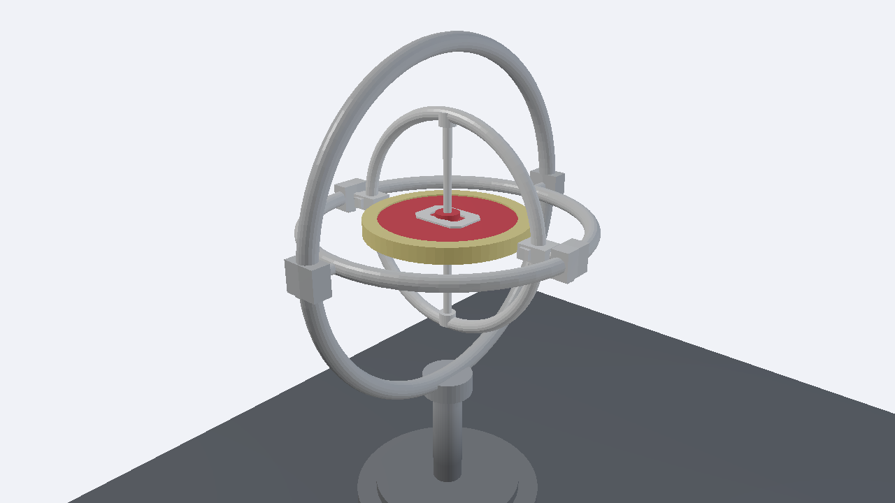 Step 6
Outer Frame Upper Snap-Lock
Top arch clicks over left/right X-axis joints.
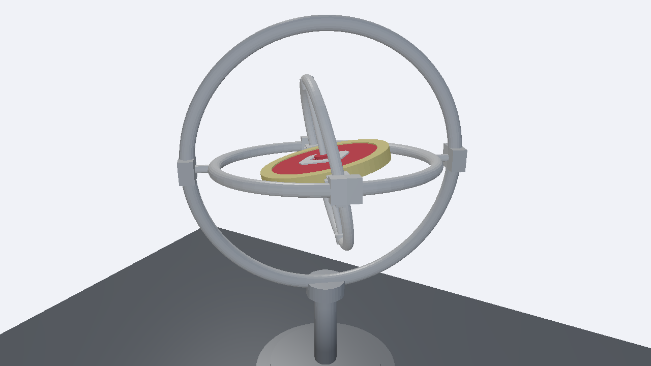 Step 7
Operational Spin Test
Full 3-axis rotation with high-speed rotor inertia.
3D Printing Engineering Parameters
Bearing Clearance
0.20 mm Free-Fit
Layer Height
0.12 - 0.16 mm
Flywheel Infill
80 - 100% (Dense)
Materials
PLA / PETG / Resin